ABOUT WATER REPLENISHMENT DISTRICT
Formed in 1959 to protect groundwater resources, the WRD mission is:
“To provide, protect, and preserve high quality groundwater through innovated, cost-effective and environmentally sensitive basin management practices for the benefit of residents and businesses of the Central and West Coast basins.”
In 2003, the WRD’s Board of Directors developed a program named Water Independence Now (WIN). This program’s goal is to protect the security of the regions groundwater supplies and phase out the need of expensive imported water. Under the WIN umbrella, there are set projects, and one key project includes the Leo J. Vander Lans Advanced Water Treatment Facility (LJVLAWTF).
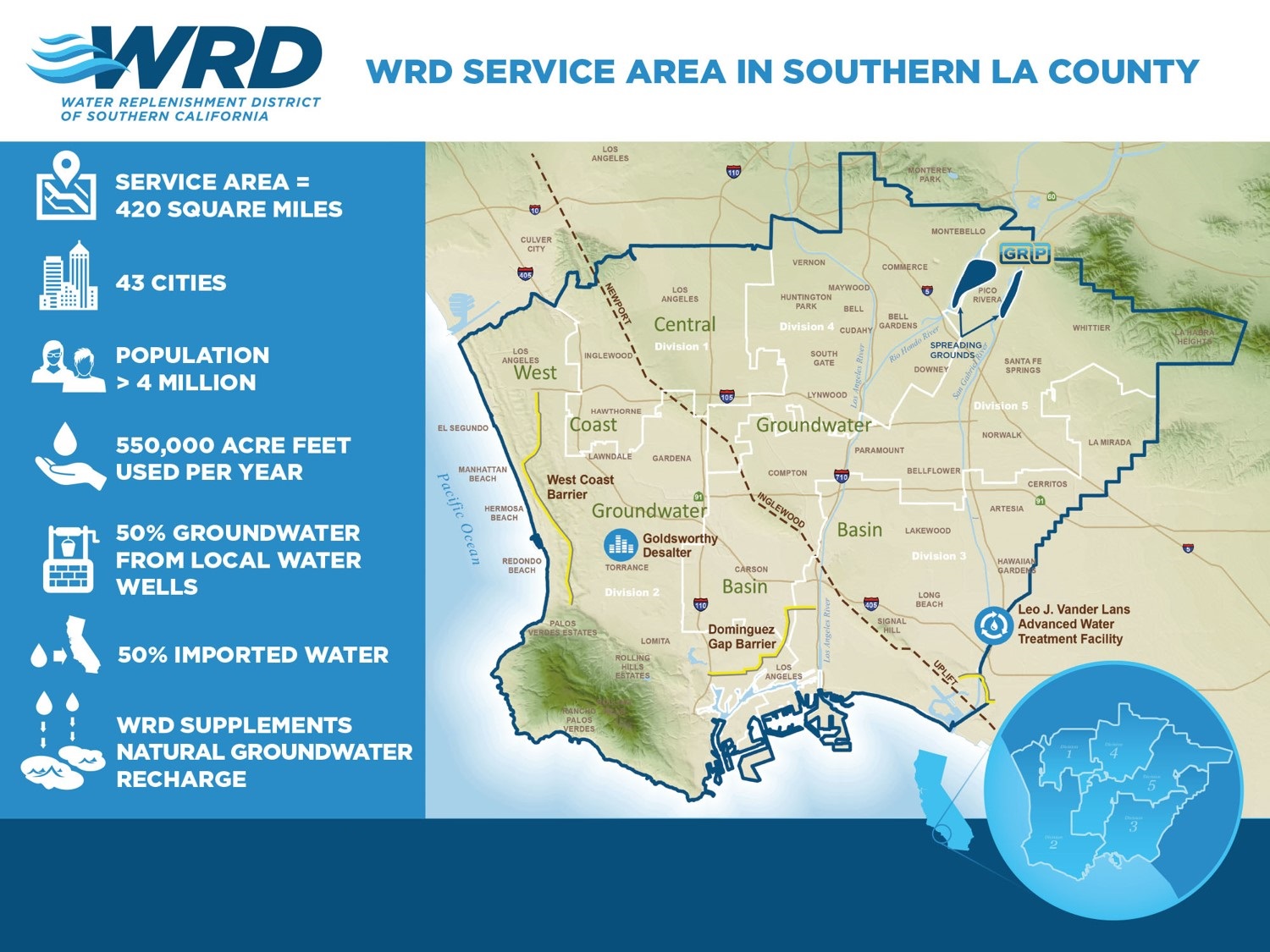
Figure 1
PROJECT OVERVIEW
The Alamitos Barrier Recycled Water project is a program to produce and deliver advanced treated recycled water to the Alamitos Gap, which protects the groundwater in the Central Basin of Los Angeles County and the East Coast plain area of Orange County from seawater intrusion (Figure 1).
BACKGROUND OF LJVLAWTF
The LJVLAWTF is located in the South East corner of Los Angeles County, approximately four miles from the Pacific Ocean, in the City of Long Beach (Figure 2). The water source for LJVL is tertiary-treated effluent from the Los Angeles County Sanitation Districts, Long Beach Water Reclamation Plant (LBWRP).
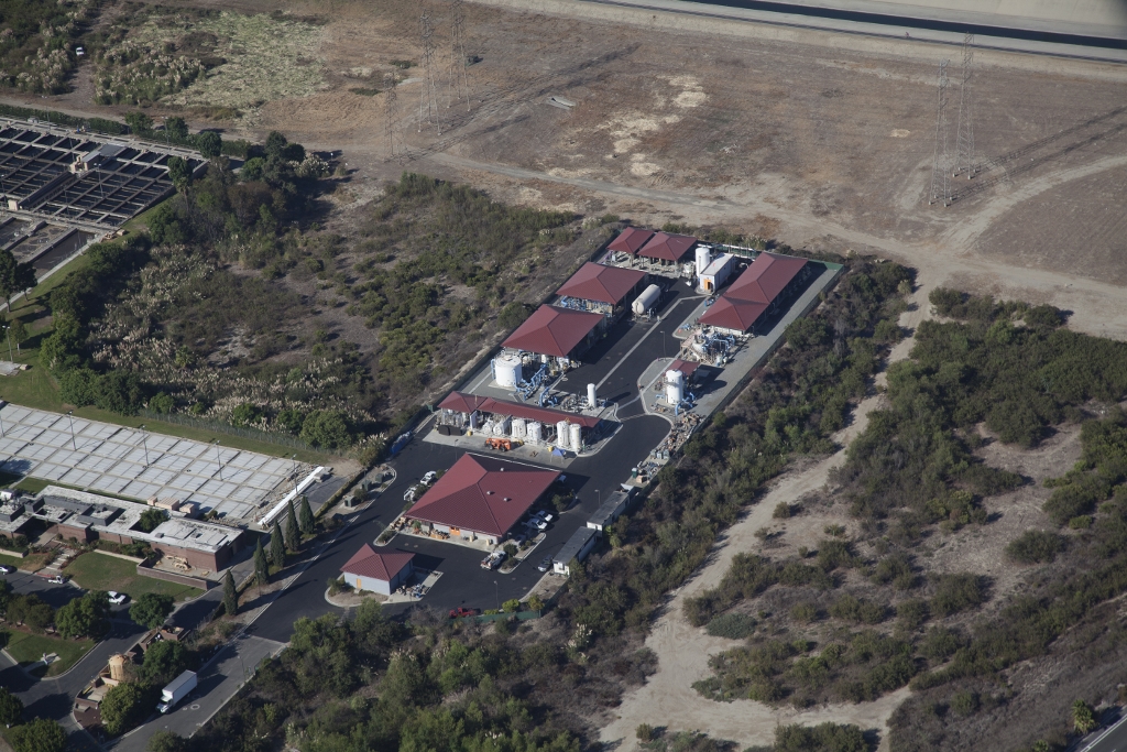
Figure 2
The project’s first phase was built in 2003 to 3.0 million gallons per day (mgd) with an overall 79% plant recovery. Prior to 2005, only potable imported water was used for injection. After 2005 and required permitting, the water injected was blended at a 50% recycled and 50% potable water. LJVL’s original footprint was designed to accommodate future expansion to 8.0 mgd and supply the barrier with 100% recycled water. The Long Beach Water Department has operated and maintained the facility since 2006.
THE STARTING POINT
On the first phase of the project (Figure 3), the 3.0 mgd treatment process incorporates Microfiltration (MF) to reduce the turbidity and silt density of the influent feed water source, a Two-Stage Reverse Osmosis (RO) system to remove salts, minerals, metal ions, organic compounds and microorganisms, an Ultraviolet Irradiation system to provide disinfection and n-Nitrosodimethylamine (NDMA) reduction, and a post water stabilization system which includes, decarbonation for carbon dioxide reduction and additional treatment chemicals for pH adjustment corrosivity stabilization.

Figure 3
DESIGN CHALLENGES
During the plant expansion design phase, one critical challenge was the sewer waste discharge. The plants concentrated brine with other plant waste is discharged directly to the County Sanitation Districts Joint Outfall sewer system then eventually is treated at the Joint Pollution Control Plant (JWPCP) nearly 15 miles away in Carson, CA. Due to the constraints in sewer capacity, LJVL was not able to exceed the peak flow rate of 528 gallons per minute (gpm). Design configuration was the driver to meet this limiting component.
PROJECT EXPANSION
For Phase 2, the plant was expanded to 8.0 mgd in 2014, with several design enhancements to increase the overall recovery from 79% to 92.5%. This state-ofthe-art design continued to meet the same peak waste flow requirement. As seen in Figure 4, the process flow diagram shows a Primary MF that incorporates a Dissolved Air Flotation (DAF) system that is used the treat the backwash water from the Primary MF. The finished water from the DAF is sent to a Secondary MF and is eventually blended back with the primary MF filtrate. This is considered a two-stage MF system. The Primary RO trains consist of two two-stage trains with a 72:36 array each with seven membrane elements per vessel. Each train has a nominal capacity of 3.66 mgd permeate flow. Each RO train has a dedicated feed pump to boost the feed pressure to meet the required permeate flow in the first stage of the pressure vessels. A second inter-stage booster pump was added to further increase pressure and ensure proper cross-flow in the second stage. The concentrate flow from the second stage is the feed water source for the third stage, RO trains. The third stage, RO, consists of three single stage treatment trains each with its own feed pump. Each train has an 11:11 array with four membrane elements per vessel. With the recovery set at 52%, each train produces 236 gpm of permeate. When one Primary RO train is configured with one-third stage train, the plant can produce up to 4.0 mgd. At maximum plant capacity of 8.0 mgd, the third stage design configuration has two trains operating in duty and one in standby. The redundancy of the stand by train increases the online factor, as it has shown the third stage trains require a Clean-In-Place (CIP) more frequently than the Primary RO.
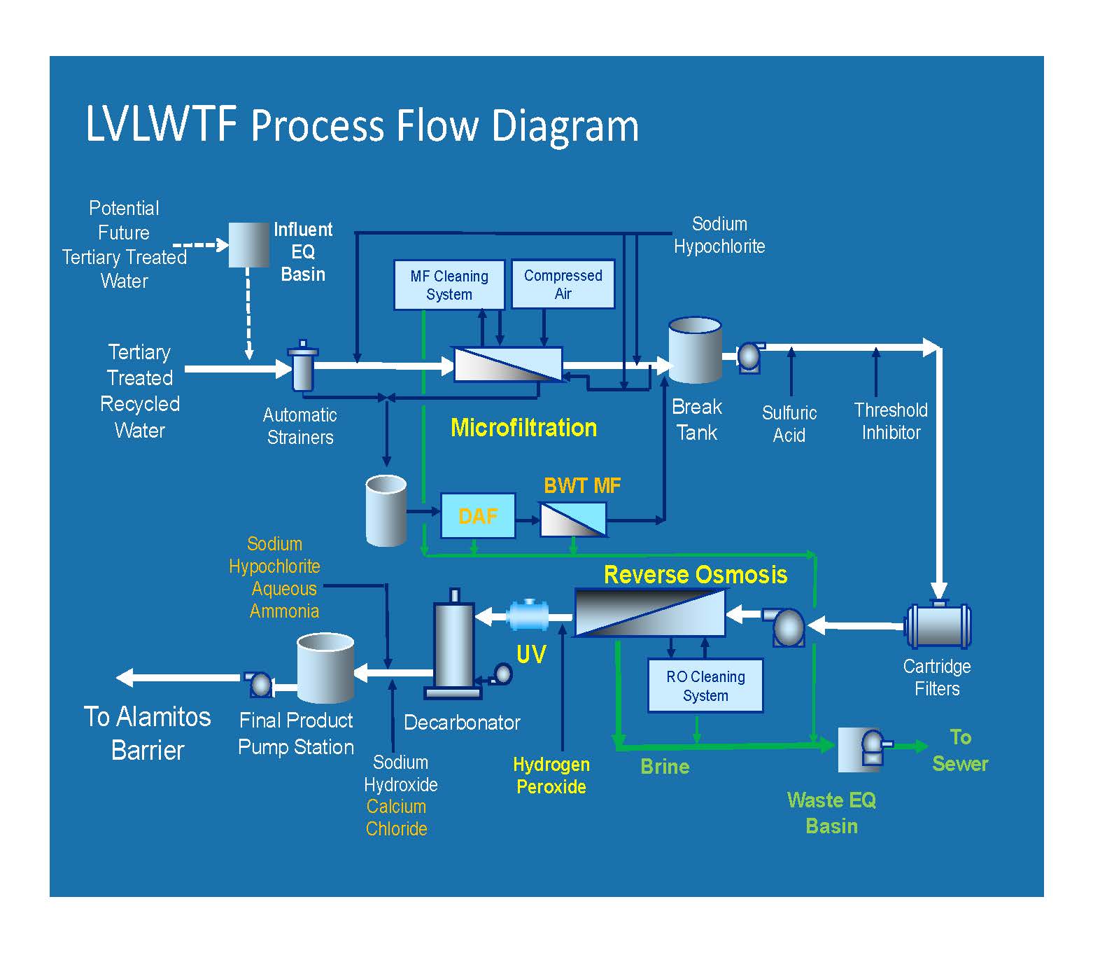
Figure 4
Down stream of the RO and immediately upstream of the Ultraviolet (UV) system, Hydrogen Peroxide (H2 O2 ) was added to provide for advanced oxidation for organics and has been highly effective in destroying 1,4 Dioxane, a synthetic industrial chemical. The Ultraviolet system is a high intensity low-pressure closed system. To accompany the nine reactor, 30 lamp per reactor train one, two additional trains were added during the expansion. Each train consists of five reactors with 72 lamps per reactor. The Post treatment/stabilization uses a forced draft Decarbonator to reduce carbon dioxide (CO2 ) and increase pH from the RO permeate. In addition to the post treatment, the plant has continued to apply sodium hydroxide for pH adjustment and adds a calcium chloride feed system meet the Langelier Saturation Index (LSI) goal between -0.5 and +0.5.
OPERATION CHALLENGES
There were two major challenges the Long Beach Water Operations team had to overcome. The first challenge was the chemical concentration change of sodium hypochlorite (NaOCl) from 5.25% to 12.5%, while still using the original conveyance piping and feed system. With the concentration change, major off-gassing began that impacted the feed system due to vapor lock. A four-step solution was applied to solve this challenge. First, sections of the feed pipe were reduced from two inches to one inch, which helped to increase the velocity of chemical feed system. Second, a recirculation system was added to keep the chemical moving and passing through a vertical flow column that vented back to the bulk tank (Figure 5). Third, the pump calibration drawdown columns were used for multiple purposes. Besides their primary function of ensuring proper feed rates, they were also used to allow secondary venting directly at the pump suction, which is also piped back to the bulk tank (Figure 6). Lastly, the original hydraulically balanced diaphragm metering pumps were upgraded with a pump head specifically to reduce off-gassing. These solutions have shown to be very effective. An insulation strategy is also being considered for additional mitigation. The second challenge was seeing declining chlorine residual at the product water plant effluent. The post disinfection system uses aqueous ammonia, which is added to the plant effluent chlorine residual for post treatment chloramination. The plant used plant effluent as a carrier water source for the chlorine and ammonia to be injected downstream of the Decarbonator. With the carrier water already saturated with sodium hydroxide, calcium chloride, chlorine and ammonia, it was discovered the additional chlorine and ammonia created a super saturated solution, eventually precipitating and reducing the size of the carrier pipe (Figure 6). The solution to this was to change the source of the carrier water. This was accomplished by using plant permeate upstream of the Decarbonator as the source. This has proven highly effective.
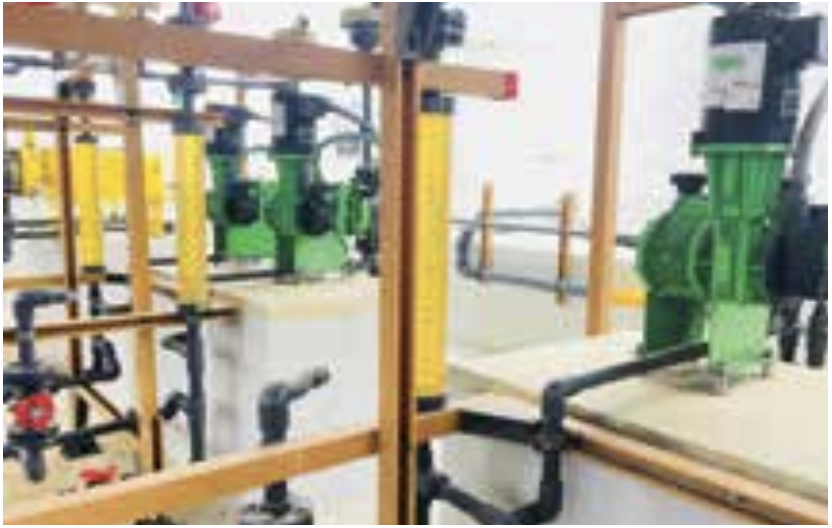
Figure 5
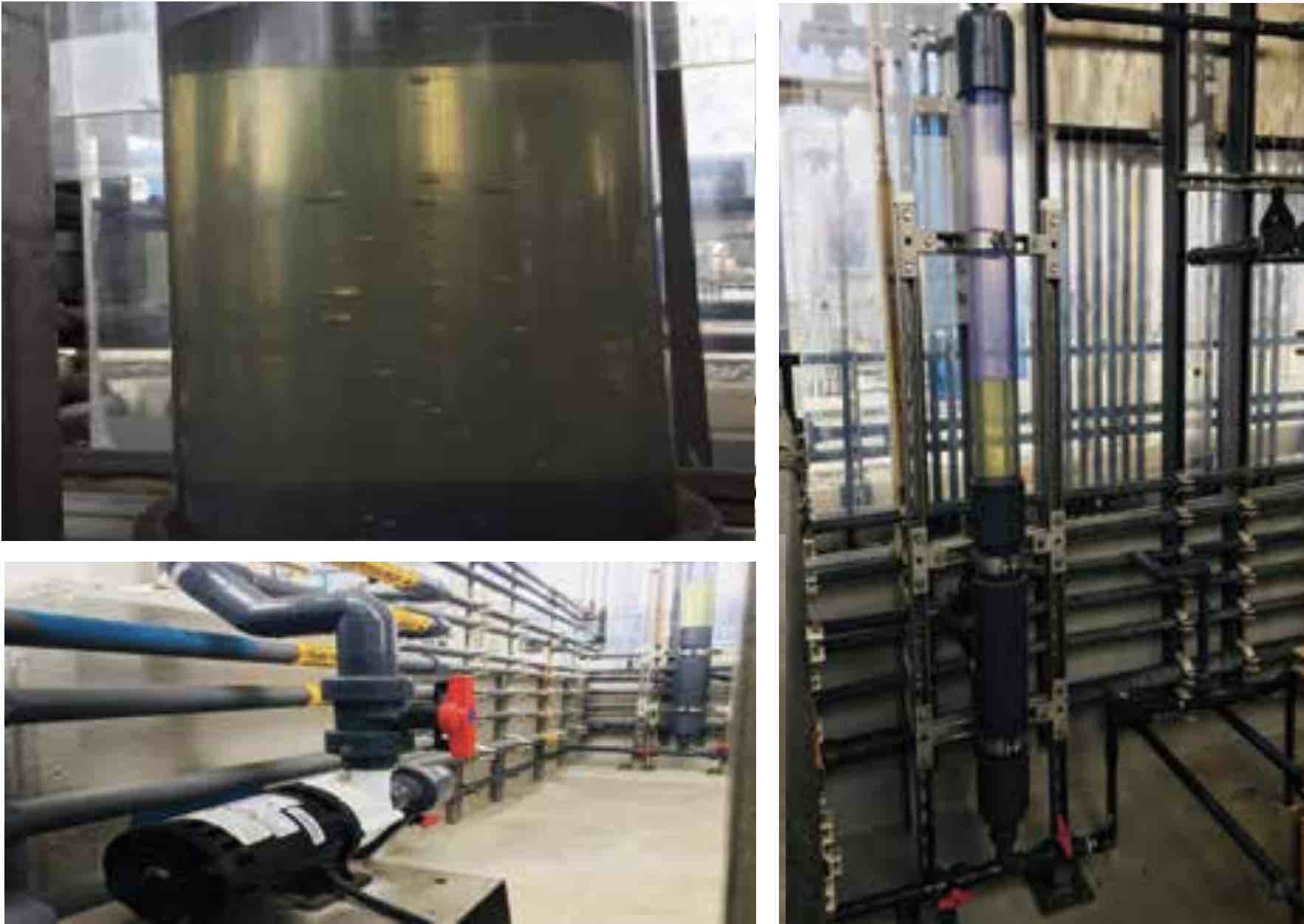
Figure 6
PERSPECTIVE
The Long Beach Water Operations team knows it’s a balancing act from the source supply to barrier demand. We have been fortunate to be able to be part of a plant expansion and have experienced the lessons learned. We are ready for any upcoming challenge while meeting our water quality targets and maximizing plant capacities.
REFERENCES CITED:
Water Recycling Requirements for the Leo J. Vander Lans Facility and the Alamitos Barrier Recycled Water Project Leo J. Vander Lans Water Treatment Facility Operations Manual 2003 Amended Operations, Maintenance and Monitoring Plan for the Leo J. Vander Lans Water Treatment Facility Expansion: Alamitos Barrier Recycled Water Project Operations and Maintenance Manual Volume 2 of 2, Trains 3,4,5 Leo J. Vander Lans Water Treatment Facility Expansion Water Replenishment District of Southern California (WRD) 2014
Check out the AWT Operator Certification & Concepts tracks on Thursday, April 11, at AC19 to learn more about challenges and lessons learned from utilities.