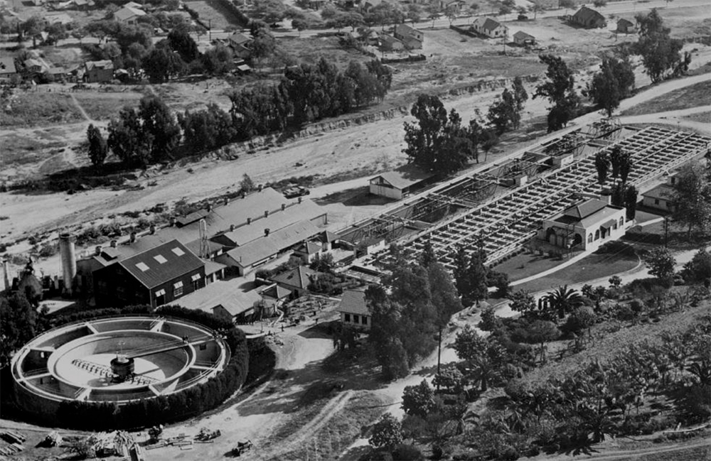
Aerial Photo of the Tri-City Plant in 1936
Part I of this series presented the history of the development of the City of Pasadena’s Tri City Sewage Treatment Plant (1887 to 1924) to provide the background and need for an updated regional treatment facility. In summary, the development of the Tri City Plant was driven by the pressures of growth and development around the City of Pasadena’s old sewer farming operation and growth in the neighboring cities of Alhambra, South Pasadena and San Marino. The nuisance issues and the impacts to neighboring properties created by the broad irrigation method of sewage treatment at the Pasadena sewer farm required the adoption of modern sewage treatment processes to solve the problems. Thus, the new Tri City Sewage Treatment Plant was designed and put into service in 1924 to serve the Cities of Pasadena, Alhambra, South Pasadena and San Marino. The Tri City Plant was operated and maintained by the City of Pasadena as part of the regional Tri City sewage treatment agreement.
Part II of this series provides the reader with a “reconstructed” photographic tour of the Tri City Sewage Treatment Plant as it would have appeared to attendees at the California Sewage Works Association’s (CSWA) 1930 Conference in Pasadena.
Part II: The 1930 CSWA Conference Tour

The Tri-City Sewage Treatment Plant as seen (at 2:15 pm) during the 1930 California Sewage Works Association (CSWA) Conference Tour
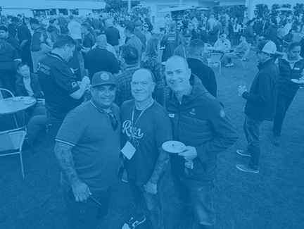
Tours of wastewater facilities have always been a part of CWEA conference programs. What better way is there to learn about wastewater collection and treatment than through a guided tour of wastewater facilities?
The City of Pasadena’s Tri City Sewage Treatment Plant was not only a popular tour site for CSWA conferences, but also for other association conferences due to its “cutting edge” technology and programs. For example, the American Public Health Association and Conference of State Sanitary Engineers included the Tri City Plant on their tour agendas. It is worth noting that the Tri City Sewage Treatment Plant was awarded the CSWA’s 1930 Award of Merit (now Plant of the Year Award), making it the first activated sludge plant to win the award and our Association’s second “Plant of the Year” facility.
The first CSWA conference tour of the Tri City Sewage Treatment Plant took place on October 8, 1930. Part of the plant tour was captured as part of CSWA Past President A M Rawn’s home movie of the 1930 CSWA conference. Rawn’s film inspired the research into the history of Pasadena’s Tri City Sewage Treatment Plant.
The CWEA History Committee is pleased to be able to present the following “reconstructed photographic tour” of the Tri City plant as it appeared to attendees of the 1930 CSWA Annual Conference. So set your watches back to 2:15 pm, October 8, 1930 – we hope you enjoy the tour!
The 1930 tour of the Tri-City Sewage Treatment Plant was led by Alfred Wyman, Plant Superintendent and CSWA Director. William Allen, Assistant Plant Superintendent and CSWA President-Elect, assisted Mr. Wyman with the tour along with A.F. Thornton, Pasadena’s Sales Agent for “Nitrorganic” fertilizer (recycled biosolids).
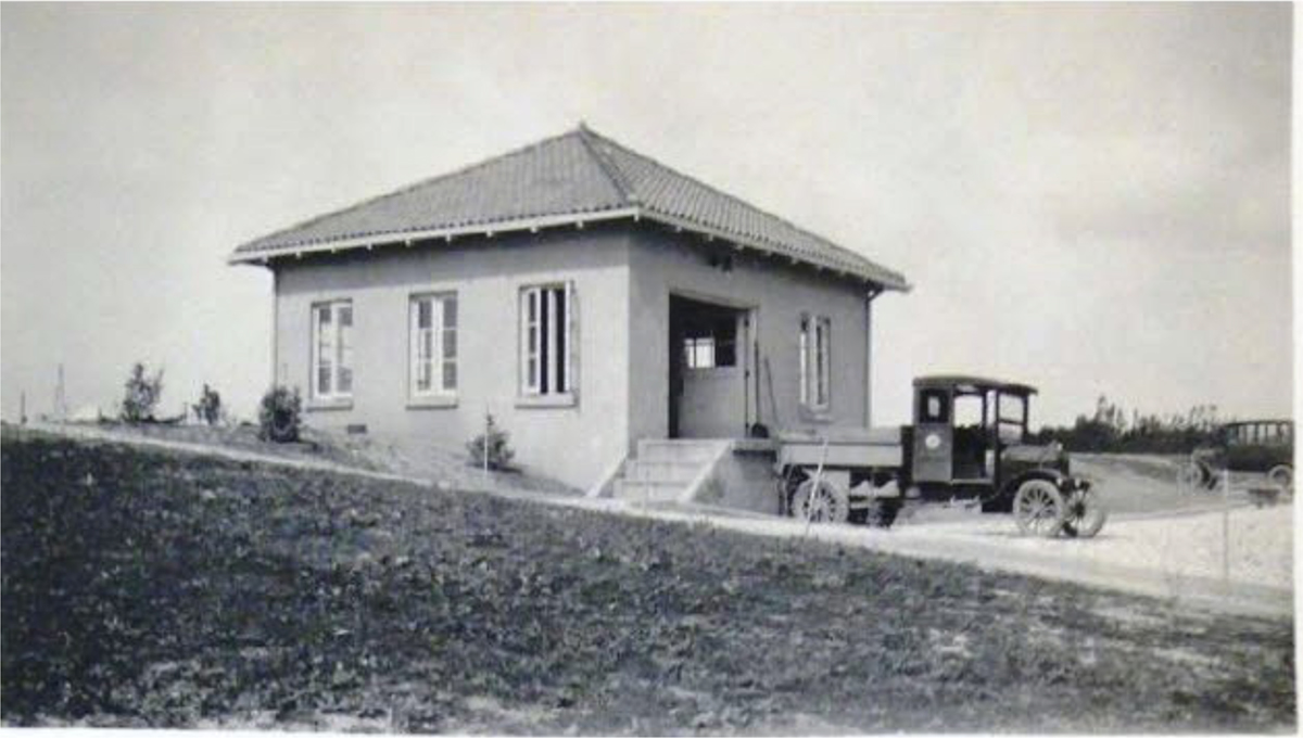
Beginning the tour at the screen house (Figure 1), the conference tour attendees would see the plant influent first passing through a bar screen used to remove any rags and large objects that might damage plant equipment. From the bar screen, they could observe the sewage passing through an 8-foot by 8-foot Dorrco fine screen (rotary drum screen) that used 1/16 inch by 2- inch milled slots to remove solids. The screenings fell from the drum screen, as it rotated, into a screening pit. The screenings were lifted from the pit by chain driven elevator buckets into a hopper and then loaded into a dump truck for disposal (Figure 2). The collected screenings were buried on the old sewer farm land for disposal.
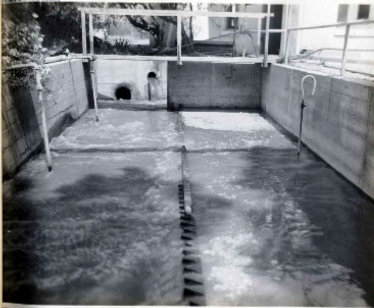
Outside the screen house, the conference attendees could see the screened sewage entering an aerated grit and oil/grease extraction tank which was 30 feet long, 10 feet wide with a 3-foot water depth. A baffle was located near the center of the tank, parallel to the flow (Figure 3). Air was introduced at one side of the tank creating a spiral flow that caused oil and grease to be retained at the baffle for removal by skimming. The tank was emptied periodically to remove grit. As with the screenings, the collected grit and oil/grease were buried on the old sewer farm land for disposal.
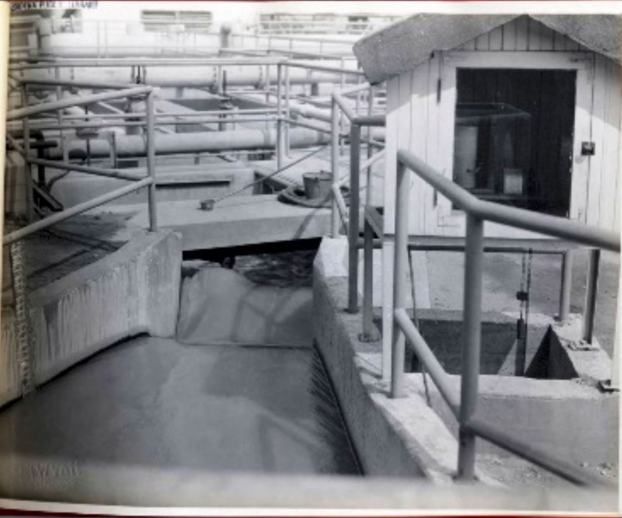
After the passing through the aerated grit and oil/grease extraction tank, the sewage next passed through a Parshall flume where the flow was measured and recorded (Figure 4).
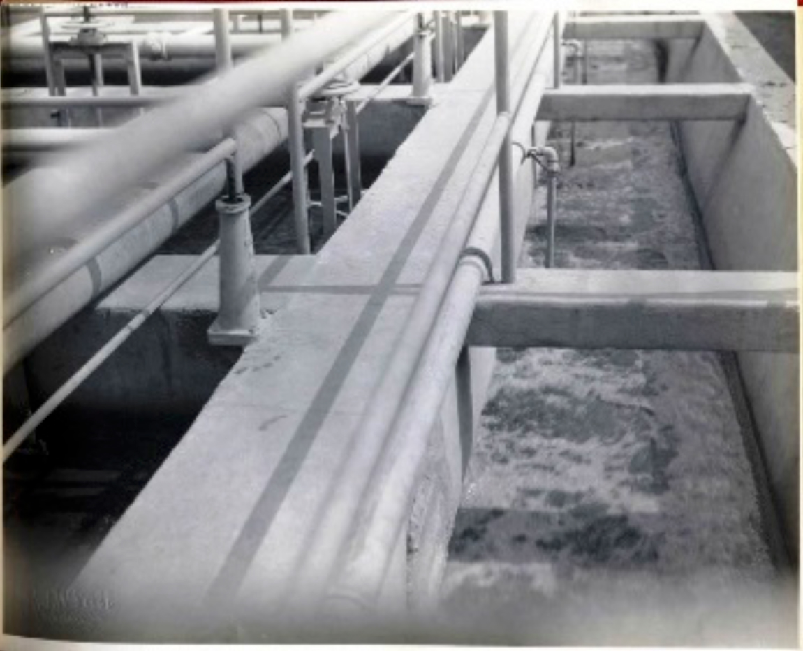
After leaving the Parshall flume, the sewage flowed into an influent “trough” (influent channel) where “return activated sludge” was introduced into the flow and the sewage was distributed to the aeration tanks (Figure 5).
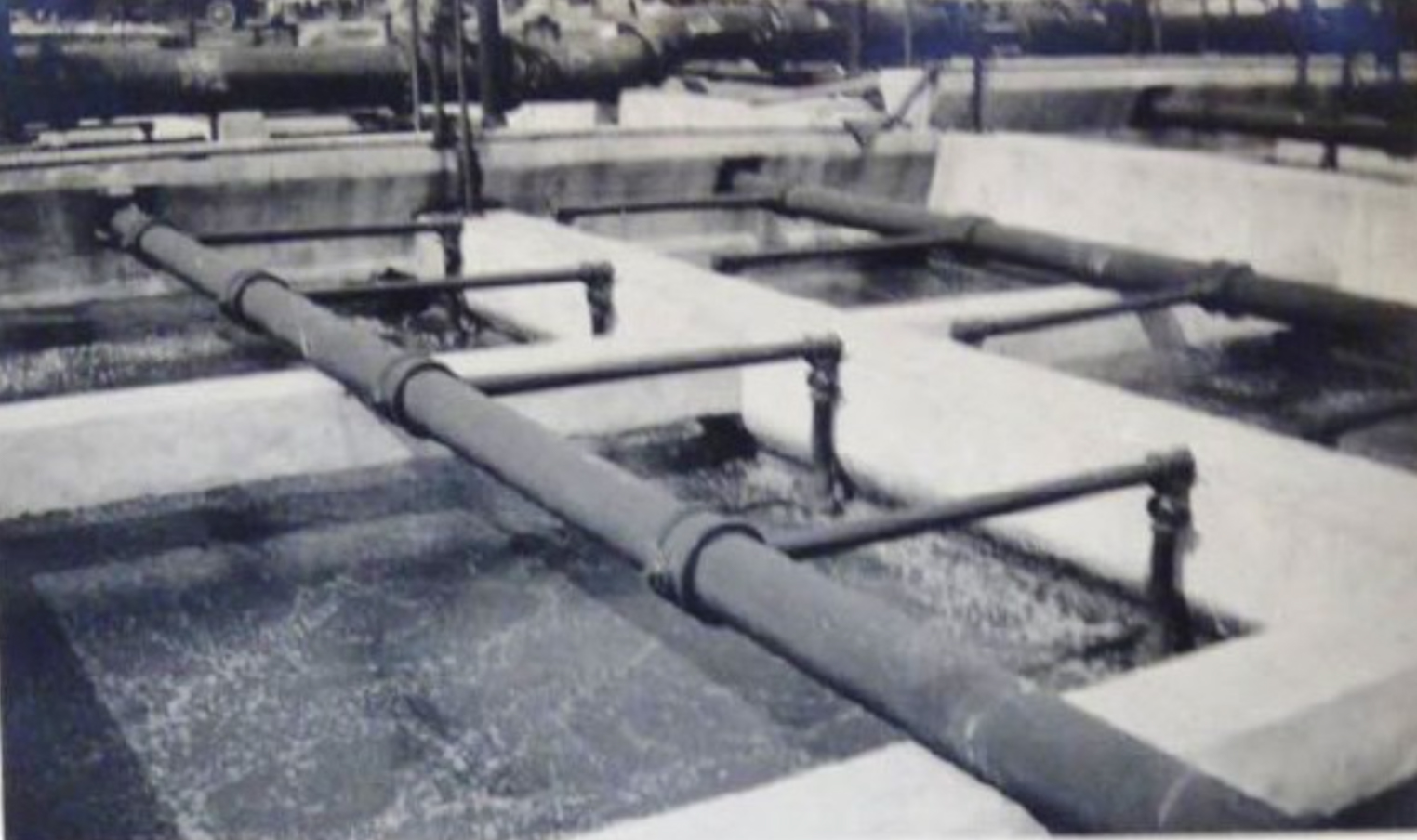
Conference tour attendees would then be shown two sets of aeration tanks (Figure 6). The first set of tanks consisted of 39 rectangular tanks, 67.5 feet long and 10 feet wide with an effective water depth of 15 feet. Thirty-three of the aeration tanks were used for aerating the mixed liquor and 6 of the tanks were used for re-aerating the settled sludge from the clarifiers prior to it being wasted (waste activated sludge) or returned to the influent channel as return activated sludge to seed the aeration tank influent. The aeration tank detention time for the mixed liquor was 5 to 7 hours and the mixed liquor contained about 1,500 mg/l suspended solids.
Air was distributed into the aeration tanks using “Filtrous” plate diffusers. The Filtrous diffusers consisted of porous plates made of silica sand bonded together with a synthetic silicate. There were approximately 3,000 of these plate diffusers in use at the Tri City plant in 1930.
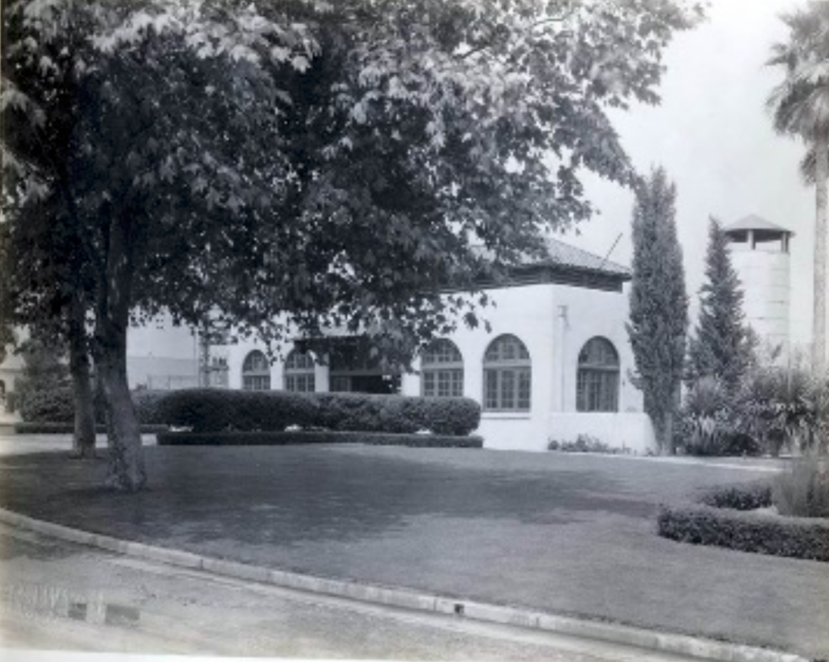
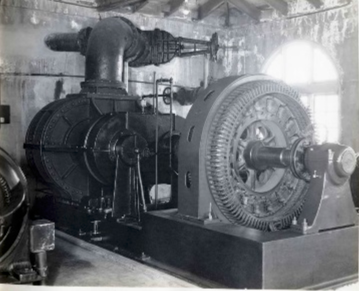
The next stop on the tour would be the blower building immediately adjacent to the influent channel and aeration tanks (Figure 7). Here the conference tour attendees would be shown five rotary type, positive air blowers with a combined capacity of 20,000 cubic feet per minute. Four blowers furnished enough air to meet the treatment requirements. This allowed one blower to act as a standby unit for rotating blowers in and out of service for maintenance and also for back-up duty (Figure 8).
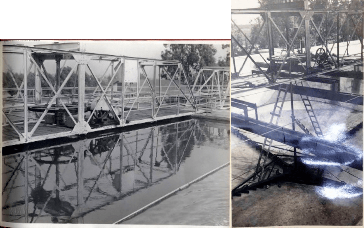
After viewing the rotary air blowers, the tour would proceed to the clarifiers. Activated sludge flowed from the aeration tanks into six clarifiers. These clarifiers were 50 feet square at the top and circular at the bottom with the floors being coned and equipped with the typical scraper or “squeegee” mechanisms to move the settled sludge to a center collector pipe (Figure 9). The scrapers revolved at a rate of 12 minutes per complete revolution. Each center collector pipe was connected to a 12-inch pipeline used for pumping activated sludge to the reaeration tanks for “reactivating” the sludge prior to it being added to the aeration tank influent channel as return activated sludge. Waste activated sludge was drawn off of the reaeration tanks to a coagulation tank for chemical conditioning. It would be explained to the conference tour attendees that the aeration tanks were originally rectangular top-to-bottom but were retrofitted with circular bottoms when the original design proved ineffective for removing sludge from the bottom of the tanks.
While at the clarifiers, the tour attendees could observe the clarifier effluent as it flowed over v-notch weirs into the final effluent channels (Figure 10). The attendees were impressed by the clear effluent produced plant process as it averaged a 94 percent removal of suspended solids.
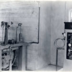
The next stop on the tour would be the chlorine bay. The final effluent was disinfected using chlorine gas from one-ton cylinders that was added to the effluent using a Wallace & Tiernan bell jar chlorinator (Figure 11).
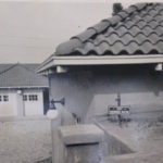
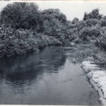
After chlorination, the effluent flowed to an effluent pump house where it was pumped for in-plant uses such as wash-down, irrigation, and cooling water (Figure 12). The effluent was also used to irrigate crops on the old sewer farm land, referred to as the Crown City Ranch. Any remaining effluent was discharged through a 36-inch pipe to the Rio Hondo at a point approximately 5 miles below the Tri City Sewage Treatment Plant (Figure 13).

After viewing the effluent pump house, the tour attendees would be shown the Tri City solids handling facilities. Waste activated sludge was drawn from the reaeration tanks into a coagulation tank for chemical conditioning with ferric chloride prior to filtration (Figure 14). Ferric chloride was added to the waste activated sludge at a rate of 5 to 7 pounds per 1,000 gallons of sludge.
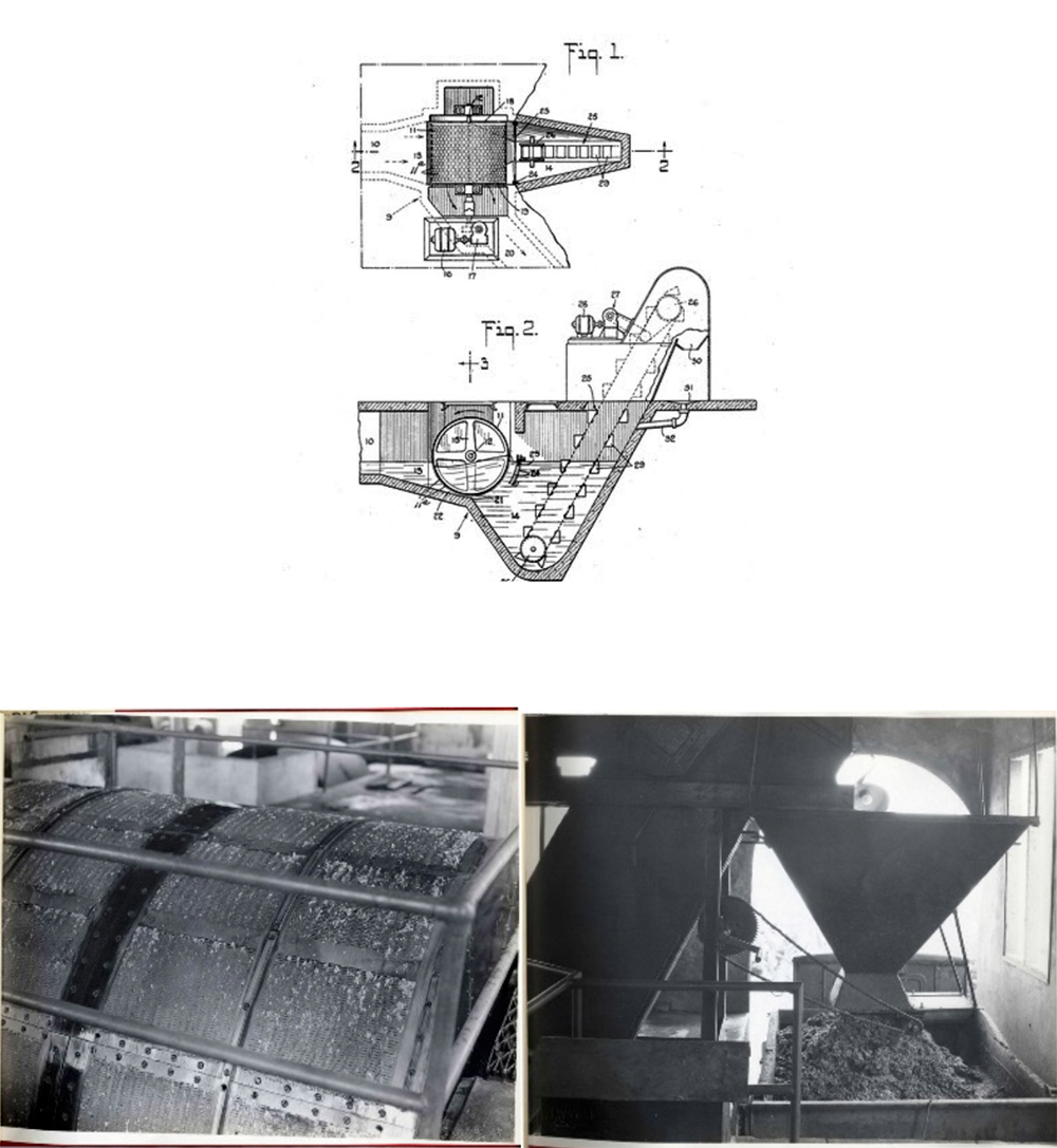
After chemical conditioning, the sludge flowed by gravity to vacuum filters (manufactured by Oliver United Filters, Inc.) where the water content of the sludge was reduced from 99 percent to 80 percent.
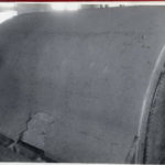
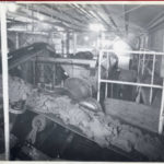
The Oliver filters used by the Tri City Plant were the revolving drum type and were 11.5 feet in diameter by 14 feet in length. The face of each drum was divided into 24 sections, or chambers, each covered with a heavy wool filter cloth supported by a monel wire backing screen (Figure 15). As the drum revolved in the tank, water was drawn through the filter cloth into the vacuum chambers with the sludge remaining on the filter cloth. The sludge remaining on the filter cloth (filter cake) ranged from 1/8 inch to 3/16 inches thick. As each section neared the scraper on the discharge side, it was automatically disconnected from the vacuum system and compressed air was applied to it to loosen the filter cake. The filter cake dropped off the filter drum into rubber belt conveyors to be fed into the rotary dryer system (Figure 16).
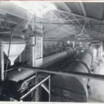
The Tri-City Sewage Treatment Plant used two double-shell revolving cylindrical dryers: one 70 inches in diameter and 60 feet long and the other 90 inches in diameter and 60 feet long (Figure 17). Both dryers were sloped 0.2 inches to the foot toward the discharge end. Flights were attached to both the inner and outer shells of each dryer. The filter cake would cascade from one shell to the other, breaking up as it dropped on the flights.
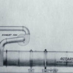
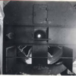
Hot gases were drawn from the dryer combustion chambers, where a temperature of 1,500 to 2,000 degrees Fahrenheit was maintained, through the inner shell to the discharge end of the dryers, where the temperature dropped to 700 degrees Fahrenheit, and then back to the feed end of the dryers in the annular space between the shells (Figure 18). The moisture content of the filter cake was reduced from 80 percent to 5 percent or less by the dryers. Dried filter cake discharged from the dryers was carried by a bucket elevator to screens where over-sized wet material was screened out and returned to the filter cake feed end of the dryers. Exhaust gas from the dryers were vented by an exhaust fan and ducting to two deodorizing stacks and washers used to control odors and dust (Figure 19).
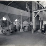
Now the tour attendees would be directed to the grinding, sacking and weighing operation. This part of the Tri City Plant was a popular feature of the operation because the tour attendees could see how processed sludge was converted into a marketable product sold as “Nitrorganic” fertilizer.
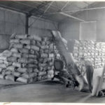
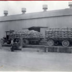
As the dried sludge left the dryers it was screened and passed through grinders and then screened again to ensure a uniform size for packaging in burlap sacks. The screened Nitrorganic fertilizer was fed into sacking bins that were used to fill the sacks. The sacks were tagged as “Nitrorganic”, “analysis guaranteed”, and “City of Pasadena”. Empty sacks were placed on a scale under the sacking bins and fertilizer was drawn into the sack until it reached a weight of 100 pounds (Figure 20). The filled sacks were stacked and stored in the warehouse at the Tri City Sewage Treatment Plant until they were sold (Figures 21 & 22). The warehouse was sized to accommodate seasonal fluctuations in demand for fertilizer.
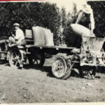
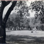
It would be explained that majority of the Nitrorganic was purchased by local citrus growers (Figure 23) and some purchased by golf courses (Figure 24), with a small amount of Nitrorganic being purchased by homeowners for use on landscaping. It was noted that Nitrorganic was listed in the 1930-31 United States Golf Association, Green Section, Dictionary of Fertilizers and Fertilizer Terms by its trade name and also as a product of the City of Pasadena. Analyses of Nitrorganic showed that it contained the following:
Nitrogen……………6%
Phosphoric acid…..3%
Potash……………0.3%
Boron……………..0.0%
The fiscal year 1929-1930 sales of Nitrorganic provided the City of Pasadena $63,016 in revenue (approximately $860,000 in 2015 dollars), which helped to offset the $108,376 cost of sludge treatment (approximately $1,480,000 in 2015 dollars).
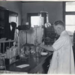
The 1930 tour of the Tri City Sewage Treatment Plant wrapped up with a visit to the plant laboratory where Albert Daley, City of Pasadena’s Chemist, would give a brief overview of the laboratory and the Tri City water quality testing program (Figure 25).
This concluded the 1930 tour of the Tri City plant and, according to all accounts, the attendees were impressed with the facilities, the quality of the effluent, and the processing of Nitroganic.
The Tri-City Sewage Treatment Plant was featured in numerous journal articles and publications, including a book on urban planning, throughout the 1930’s and up to 1948 when the plant was taken out of service and completely demolished. Today there is no trace left of this “forgotten facility” except for collection system piping that once served as the old outfall system to the plant.
The CWEA History Committee wishes to thank the Pasadena Public Library and especially Dan McLaughlin, for their kind assistance in providing archival material that made this reconstruction of the 1930 CSWA Conference tour of the Tri City Sewage Treatment Plant possible.